Sunday, May 26, 2013

Quadcopter build : Plan C

With some nice calm days I was able to get outside and do the maiden flight of the Quadcopter. Flight is a very loose term for what actually occurred  I had a couple of good flights, but also a couple of really decent crashes when I tried to run before learning to walk. 

The Quad frame stood up well to the abuse, the zip ties did their job and reduced the damage. But after a while I though that I should try and save this frame for FPV and learn on a cheaper frame. 

So I transfered all the gear off the BlueskyRC frame to the RCtimer quad frame that came with the motors and ESC, it only took aout 30min.  


RCTimer frame all set, I also put the helicopter landing gear on the frame to help with "heavy" landings.  


The battered BlueSkyRC frame now stripped down ready for new booms and a pilot who can fly :)


Wednesday, May 22, 2013

Quadcopter build : PLAN B Complete .... time to crash ... I mean fly

So after another night of tinkering away I now have a complete quadcopter .... yeah for me. This is most likely the last time you will see it in such good condition ...

Lets go over the additions and finish up of the build first. After finishing the last set of power leads required I moved on to creating a battery holder. I used popsicle stick and some thin pine wood to make this simple plate. 


The plate is hot glued to the bottom of the center frame. I Used hot glue so if I need to remove it I could. The plate has a gap to allow the power lead enough room.


Hot glued down and velcro stuck down. It gives a nice sturdy platform and also plenty of battery postion options to get the correct CG depending on what I end up putting on the frame.


Next build item was the top plate to hold the kk2 board and the receiver. I used 4mm balsa wood for the top plate. I then needed a way of attaching the plate to the frame. I used the trusty popsicle stick, four were cut to length and then using the already laser cut hold as reference drilled and screws to the frame. That additional advantage was that the screws used were long enough to go on to the booms so it also holds the quad together.


 First mount rail complete... three more to go.


4x10x50mm strips of balsa wood doubled up was used to raise the mounting location of the top plate to give gaps for wires


Top plate all glued and screwed to the frame. As you can see it give a large flat area for mount electronic.


A test fit of the supplied "cage" to protect the kk2 board.


Next up I mounted the kk2 board on the same foam and velcro setup used on the home made quad. The receiver was also velcroed on.


All the electronics now on the Plan B build.


The next step was to mount the motors. I didn't use the supplied mounts, I just drill holes and used zip ties. I seems to be be very strong and rigid. It also hopefully reduced some of the weigh that I added with my modifications.  I used zip ties to hold the motor booms centered.

So here is the final Plan B Build.... take a final look as this may be the last time it looks like this.

I will hopefully get some calm fine days soon so I can go and have a go and flying it. Wish me luck.


Tuesday, May 21, 2013

Quadcopter build : PLAN B

One step forward and two back.

I got the big old home made quad in the air. I rediscovered I am complete crap at flying and I had a few rough landings, All I was trying to do was some basic take off and lands, and hovering. All of which wasn't so successful. However one key learning was that the home built was BIG & Heavy for the spaces I was planning on learning to fly. I also noticed flex in the booms. So after considering my options I decided to shelf the home build for now and build on a smaller proven platform until I get my flying skills up.

That meant the BlueskyRC frame was going to get use earlier than first thought.


I love laser cut plywood objects and the BlueSkyRC frame is very well done. The frame snapped easily. The main frame parts CA glued ready for the spars and booms.


Since its really hard to get 10mm square wood rod, I am using 10mm aluminium U section. Its light and very ridge over the lengths needed.

I ended up changing the measurements from standard, the booms are 400mm and the internal one are 350mm. This will allow me to have the ESC in the gaps and give a clean look. I changed to these measurements after doing some testing fittings and unfortunately had to cut another set of u section. But even at this stage it feels much ligher and more ridge than my home made one.


The U Sections cut and filed to remove and sharp edges.


The booms and frame parts laid out, this is the small sized one the internal ones increased in length 50mm.


A quick fit together and comparison to the home built quad, yes quite a difference.


Time to take all the electronics out of the "old" quad and fit into the new one.


This also included the heli0500 landing gear. Once the center was found and the middle frame section was centered the legs were zip tied in place.


Already for the electronics to be included.


I am a sucker for punishment, I redid the wiring on how I intended to do it the first time but wasnt able to as I was missing parts and did not want wait first time around. My aim was to make it very modula. This will allow any part of the power system to be easily replaced or used in another flying machine.

This required cutting off the leads I had soldered on the motor side of the ESC to add 3.5mm bullet connectors. That was repeated on all 4 controllers. 

All leads were cut from the ESC leaving 20mm. Bullet connectors were then soldered on and heat-shrink applied.


All 4 ESC complete with the new bullet connectors and heat shrink.


The test fit, I didn't want to just have the ESC zip tied to under carriage. I still want a nice clean look like I was getting with the home build.  The ESC's fit snugly between the frame either side of the main frame elements. The underside will have balsa wood glued to the spars and I will make a balsa top plate to complete conceal the ESC.  Yes a little OCD.


Next was to make the leads to go from the ESC to the motors that would thread through the frame. I needed 12. I reused the leads that I cut from the ESC and they were the perfect length when cut in half, got to have a bit of good luck every now and then. So a lot of soldering, I only got the first 6 done before calling it quits for the evening..... "Game of Thrones" was calling. 


First six complete.


The mess left after the evenings destroy and remake.


Monday, May 20, 2013

Quadcopter Build : Battery & base calibration

Well after a long wait the Turnigy 2200mAh 3S 25C Lipo Pack finally showed up. So after charging the batteries it was time to do some of the final assembly.


I got 2 other packages today as well, One was a larger number of HobbyKing 8x4.5 props in bright colours, went a little overboard... but since the shipping wait is so long I didn't want to run out, as I expect to crash... a lot initially.


This box also included 4 grub screw prop adaptors.  After doing more reading using prop savers on the quad was rejected. I like these as they are a good snug fit and sit close to the motor bell. I hope this will reduce the risk of bending a motor shaft.


The other box contained backup plan "B" This is a h-Quad from BlueSkyRC. I really liked the H-Quad. So if my home built one is to heavy or just doesn't fly well I can revert back to this.


NEAR DISASTER 
Well that was close, for whatever reason after I connected that battery for the first time a nice blue bloom came bellowing out of the Quad ...... PANIC.
I had not idea why, I had triple checked the wires and polarity. I was hoping it wasn't and ECS as I would have to order another and that would delay the build another 3 weeks!

Much to my surprise and relief it was the power distribution board that had gone up in smoke, No idea why.

Luckily I had enough 3.5 connecters to make up my own power harness, it took a while, and after finishing it I realised I had not added any JST leads & plugs for other accessories. (Batt voltage, LED lights) So will need to retrofit them.


Now the big test, All powered on more more blue smoke ... phew. Still need to test the ESC to make sure they were not damaged. Now that I had power I binded the receiver to the transmitter.  After doing a quick google search I found the instructions (Remember I am a complete newbie so have to learn everything). All done. 


Very happy that at this stage everything seemed to be ok after my blue smoke episode, I we ahead and mounted the KK2 board. I used the foam from the shipping box that the KK2 was shipped with and velcro. The foam was glued to the center of the top plate and them strips of velcro glued to the top of that. I then used the self adhesive velcro strips on the back of the KK2 board. This will change but I think it will be a good enough to reduce vibration from the frame.


After searching and not finding a lot of easily found information on how to wire the 9x8c V2 receiver to the KK2 board, I just went ahead and did Ch1 to pin set one on the kk2 board and followed that for the 4 channels. Turns out that is correct. Just remember that the outside pinson the kk2 board are the grounds.

I confirmed the channels were correct by connecting up the receiver as stated above and powered the system up. On the KK2 board there is a setting to "Test receiver" This shows what the board is thinks the transmitter is doing. This was great to test everything, It showed that everything was connected to the right channels.

While I was doing this I also set the sub-trims on the TH9x so that when the transmitter control were in their neutral setting the KK2 board values showed "0"

Great overview of setting up a kk2 board can be found here

Once that was complete it was time to mount the receiver, the trusty velcro was used.


I then connected up all the motors and the controllers to make sure all the motor were spinning in the right direction. I had to change a few, all you have to do is just change two connections over.  All motors now running in the correct direction, of course this was done with props off.


Now I have some blue thread lock I took off the motors and applied some blue tread lock to all the mount screws then used 4 zip ties on each to mount them to the booms.  While I was doing that I also mounted the new prop adaptors and applied thread lock to the grub screws. Hopefully all are now nice and secure and wont vibrate loose.


I ordered a set of 500 helicopter landing gear when I ordered my BlueskyRC frame, They seem small for my large h-Quad, but will suffice as landing gear. These were zip -tied on to the bottom plate. Two holes were drilled through the bottom plate and one through the landing gear.


All zip tied in, 


After all this was done I balanced a set of the 8x4.5 props and put them on the quad .... I needed to see if it would fly, well at least leave the ground, as I am a little worried about the weight of my frame when I see its size compared to the BlueskyRC Frame that uses 8x4.5 props.

So in the garage I did a quick spin up and it did left off but I estimate at about 60% throttle. I then tried the 10x45 props and it was about 45-50%, remember these were 2-4 sec flights, So the good news is that it will leave the ground.

Once I confirmed that it will fly .... well leave the ground I started to snap together the BlueSkyRC frame. I have learnt a lot from the scratch build and depending on how the flights go I might just transfer everything over to the small, lighter BlueskyRC frame. Testing will prove out the best direction to go.


Sunday, May 19, 2013

Quadcopter Build : Power harness & frame

After a long wait another large box showed up from HobbyKing, It was the main one I was waiting for. It had silicon wire, connectors, heat shrink, Transmitter, Servo leads, KK2 board and other bits to make up to the full weight for shipping.  Luck would have it that it showed up on a Friday, which meant I could get stuck into it that night.

During the week I purchased some organiser trays to hold all the bit that are starting to gather during the Quad build. Need to keep them separated from the other work going on in the garage.


Right time to kick this next part of the build off... First task was to get a work space, very limited in the garage at the moment ... well actually always. So the portable spray table was used. I placed my old work desk top on the table (Actually just a door), worked perfectly. I then laid out the parts and tools required.  


I set the iPad but to capture some time lapsed footage of the evenings progress, unfortunately i forgot to full charge and only got half the build ...Doh.


 All the new bits laid out and getting sorted.


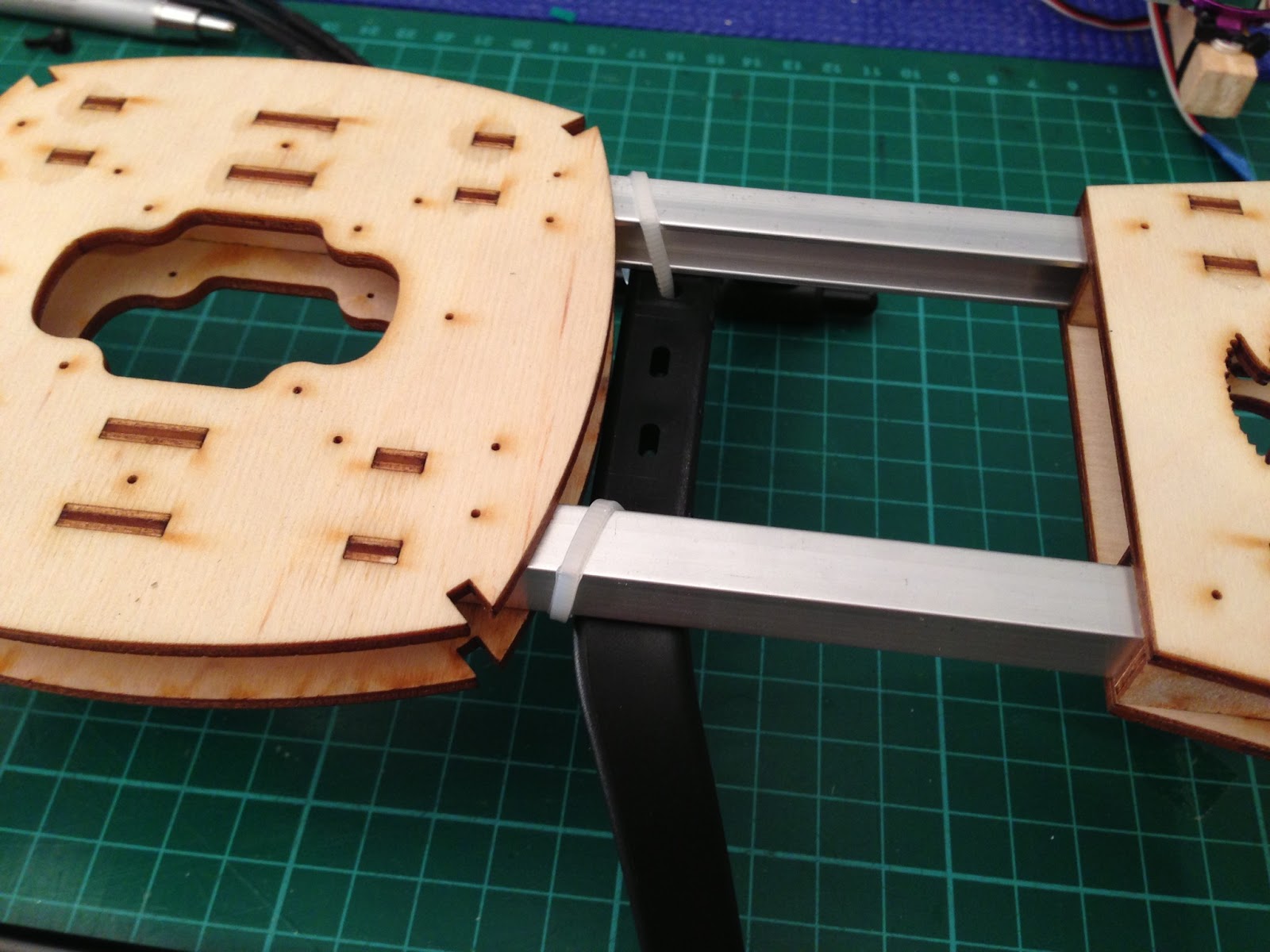
First step mount the motors, that required the mount plates screwed on and then zip tied to the booms, I realised that I didn't have any thread-lock  so only used 2 zip-ties to hold them in place until I can get some thread-lock and apply to all the mount screws.


With four zip-ties holding them in-place the motors are very securely attached to the booms.

I was getting a sore back working on such a low work desk ... so a little improvisation was required. I used a some speaker stands and my hotrod seat from the Ratty-T build as a seat ... work perfectly for this old man.


I now need to work out where the ESC were going to ne mounted and work out the wire lengths I needed.


Wires cut and the end trimmed ready for pre-soldering.

Using my new supa-dupa soldering iron I made quick work of soldering on the 3.5mm bullet connectors. After waiting all this time for the shipment I realised that I did not order enough ... grrr. That changed how I wanted to wire up the power harness. But I will change it one I get some more and have a few flight under my belt.


One end fully complete, only 11 more to do.

All wire now have 3.5 female bullet ends to connect to the motors.


The next job was to add bullet connectors to both the ESC and the other end of the wires. I wanted the ability tio easily remove and swap items in the quad, however since I didn't order enough I decided to splice the wires and when I get more connectors I can change that later.


Splicing and soldering, before heat shrinking.


The ESC also required connectors soldered on the power leads to connect to the power distribution board. Below is the finished power harness, and the test fitting in the frame.


A quick comparison to the SM450 sized frame.

The next build task was to create plate to cover the power harness and mount the receiver and kk2 board. Using balsa wood I made two rails 12mm wide and 8mm high.

I then cut the top plate out of balsa wood and covered the full length of the frame. The width was correct as the frame width was based on 100mm wide ply and balsa.


The rails were then CA glued to the top plate, they were shorter to allow a gap either end to allow the routing of the power harness to the motors.


The top plate sitting on the frame, you can see the small gap either end to allow for the power wires.

 Next I zip-tied the power harness in to the frame, I then did a lot of test fits of the top plate to see where I needed to add extra strength to the balsa-wood.


On the underside and center I added another rail so that rested on the frames main center cross member and cut notches to allow for the power wires that went over the top. I also added in some popsicle sticks at either end and also in the middle for where the nylon screws would be if use those to mount the KK2 board. 

 On the top side I added popsicle stick on the edges where I planned to have zip-ties holding the top plate on. I did not want the balsa-wood crushed. A couple of holes were cut for the ESC controller leads.

Getting ready to zip-tie don the top plate.


One end zip-tied down and you can see the power leads out the gap and the double thin zip-ties used to hold the top plate in place.


Connected up the power leads to the motors and zip-tied them in-place to give a nice tidy look.


A mock up with the KK2 and receiver sitting approximately where they will be mounted. Very happy so  far with the nice tidy layout and having most of the wire harness hidden.


During the weekend I also got Phoenix4Rc and the TX9 playing together to do some flight simulator practice. Which only proved that Im a crap flyer and need a lot of practice.

 One of the other items I got from Hobbyking was the ATMEL programmer that is used to update firmware. The KK2 board was shipped with version 1.2 and the latest and recommended version is 1.5. After watching a few good youtube videos It was a simple task to up date the boards firmware to 1.5.

While it was powered on it gave me a change to look at the menu structure and settings.


Here is the time lapse video that didn't quite work out ..


I am now waiting on other packages to arrive before the build can continue, the main one is the batteries.